FAQ
How does the temperature protection work?
Temperature is sampled at 20Hz. The internal microcontroller reads the diode temperature and automatically modulates the laser power when it reaches 47.5°C to scale the power. At 49°C the microcontroller will shut off the laser until the temperature is at a safe working temperature.
Is the TTL line RS485 voltage tolerant?
The TTL line is protected from voltages exceeding 5Vdc. The RS485 standard specifies a maximum open-circuit voltage of 12 Volts: signal levels of ±5v, ±10v, and ±12v are all commonly seen depending on the voltages available to the line driver circuit.
The TTL line does not support a differential voltage signal (i.e. ±V)
The Digital modulation circuit will clamp voltage levels above ~ +6 VDC, and there is circuit protection that will prevent damage if voltages up to ~ +9.8 VDC are applied to the TTL signal
The laser may not perform to published specifications for TTL / reverse TTL in regards to speed and performance if there is a differential voltage applied (±V), or the voltage applied to the TTL line exceeds ~ +5.4 VDC
Can the Skate laser be triggered via a TTL pulse train (0vdc = off. 5vdc = on)?
Yes. We cannot guarantee it will work with all systems and may be limited by the frequency and duty cycle. We recommend testing it with your system.
It works with TTL inverse and normal. The TTL can be switched from inverse or normal via RS485 commands.
Can Skate lasers operate solely with RS 485, or do they also require TTL?
Yes, Skate lasers can operate with RS485 or TTL. You can disable TTL and use only RS485 if that is your preference.
Can you give us some images of what this laser looks like on something, e.g. what it looks like projecting onto a wall or floor?
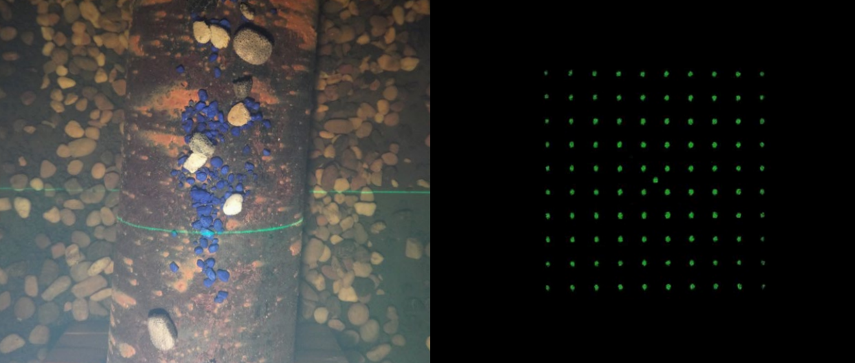
With a grid pattern, how do we adjust for height off the seabed, or do the dots remain fixed at equal distances?
Due to the divergence of the beam, the dots do not remain at a fixed distance but rather increase and decrease with altitude. The beam angles can be found here.
To find the distance between the dots there are multiple methods SubC is aware of, and there may be others:
You could have multiple lasers intersect at a known height above ground, this could be done by having a line laser placed so that when the line matches up with the edge of the dots you are at (X) altitude.
Alternatively, if you have an NMEA altimeter, you can use that information and with a known altitude, you can then calculate the measurements between the dots. Some NMEA Altimeters are compatible with Rayfin Aux Ports.
It is possible to have a camera and laser system calibrated and use software to extract measurements. SubC doesn’t own any software of this type but may be able to help you source software if you have some specific requirements.
How do you take into consideration oblique angles?
As for the projection of the dots, it is just a projection so there is no compensation for oblique angles unless it was mounted to a gimbal or tilt mechanism that could mechanically compensate.