DCS cable grips are used to provide anchor points for key locations on the system and to protect device bulkheads in the event of a cable snag. The grip distributes force along a long section of cable to prevent any kinks in the cable and to allow for a removable and adjustable attachment/tow point.
2
For more detailed instructions, refer to the video: Cable Grip Setup. (Note: these instructions apply to both the orange and yellow cable grips provided by SubC)
3
Before starting the cable grip installation, it is important to mark the cable as shown in the diagram below. The marks can be added to the cable using a marker.
4
The D in the diagram stands for the cable diameter. The diameter of the blue camera cable is 9mm, and the diameter of the yellow altimeter cable is 8.33mm.
5
The first 8D (8 x Diameter)distance should be measured from the Wrap Starting Point to the leading edge of the first marker placed on the cable. All subsequent distances should be measured from the leading edge of the previous marker to the leading edge of the next marker. In the diagram perspective, the leading edge would be the “left” side of the marker in this case.
6
Continue adding markers to the length of the cable to span the distance that the cable grip will cover. If you add too few or too many marks, you can simply add more or remove them as necessary when moving down the cable during wrapping.
Kevlar Data Cable(9mm diameter)
8D
72mm
6D
54mm
4D
36mm
Installing the Cable Grip
#
Attaching the grip to the cable
1
Select a location to install the cable grip. Refer to this video that demonstrates the amount of slack required in the cable to ensure that the grip holds all the tension.
2
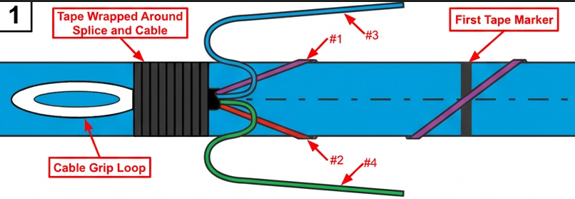
Secure the cable grip to the cable with tight wraps of waterproof tape around the heat-shrink-covered splice area.
3
Observe the four legs of the cable grip. When looking along the cable toward the grip loop, leg #1 is the bottom-right strand, leg #2 is the bottom-left, leg #3 is the top-right, and leg #4 is the top-left. (The colors in the diagram are to help visually identify the four legs
#
Leg #1 installation:
1
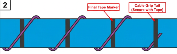
Begin wrapping leg #1 in a helix shape along the length of the cable, crossing over at each tape marker. Note: the leg wrap should follow a left-handed thread spiral, as shown in the diagram. You can use a piece of tape wrapped around every few tape markers to hold the leg in place as you continue down the length of the cable.
2
Wrap a piece of tape around the excess length of leg #1 that hangs past the final tape mark.
#
Leg #2 installation:
1
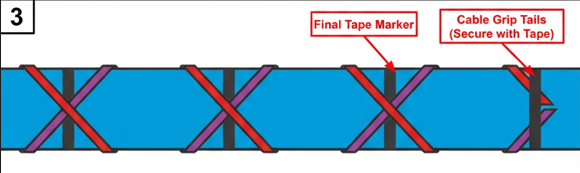
Similar to leg #1, wrap leg #2 along the length of the cable in a helix shape, with the spiral going in the opposite direction as leg #1. Both legs should cross each other at the tape markers along the ca
2
Secure the excess length of leg #2 using a piece of tape.
#
Leg #3 installation:
1
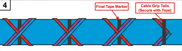
Leg #3 is installed the same way as leg #1 with the helix spiral wrapped in the same direction.
2
Secure the end of leg #3 with a piece of tape.
#
Leg #4 installation:
1
Leg #4 is installed the same way as leg #2, with the helix spiral wrapped in the same direction.
2
Secure the four bundled ends of the cable grip with multiple wraps of tape.
3
Once the wrapping is complete, wrap two layers of tape around the cable and cable grip, weaving every 3-4 inches along the length of the cable back towards the grip eyelet. The installation is complete.