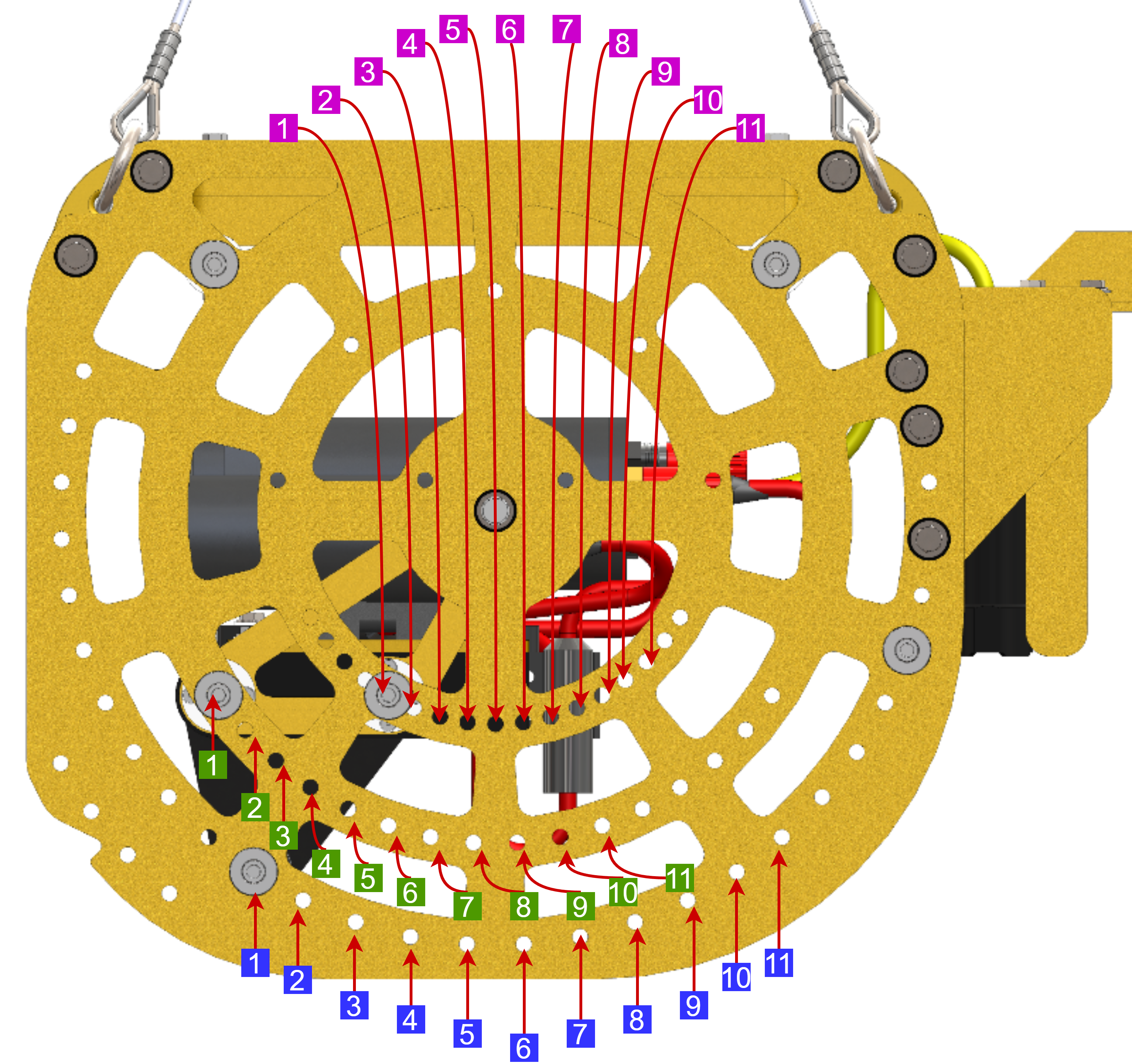
The camera pivot assembly has eleven (11) possible angular positions ranging from 15°-90° below the horizontal (0° line) shown in the figure on the right. The red line in the figure indicates the direction that the Rayfin is facing
The adjustment holes are angled 7.5° apart from each other.
The figure shows the camera in position 1 since the three (3) pivot assembly screws are in the ① position on each row of adjustment holes.
The table below shows the corresponding camera angle for each assembly position.
The yellow circles highlight the bolts that hold the front protection spars in place. These spars need to be moved when pivoting the camera to a new position. Note the (x4) angle adjustment holes between the yellow-encircled bolts. This gap should be maintained when moving the camera and protection spars (i.e., the camera line of sight should be centered between the protection spars). This ensures that the field of view of the Rayfin and other devices is unobstructed by the spars.
The purple circle highlights the rear support spar bolts. This spar needs to be repositioned to the front side of the DCS if the camera is moved to any position in the range ⑦-⑪. The position for this spar can be selected by the user; it should be placed such that it protects the equipment from any potential impacts.