The camera/LED assembly pivots about the pivot bolt in the center of the support panels.
|
|
|
1
|
|
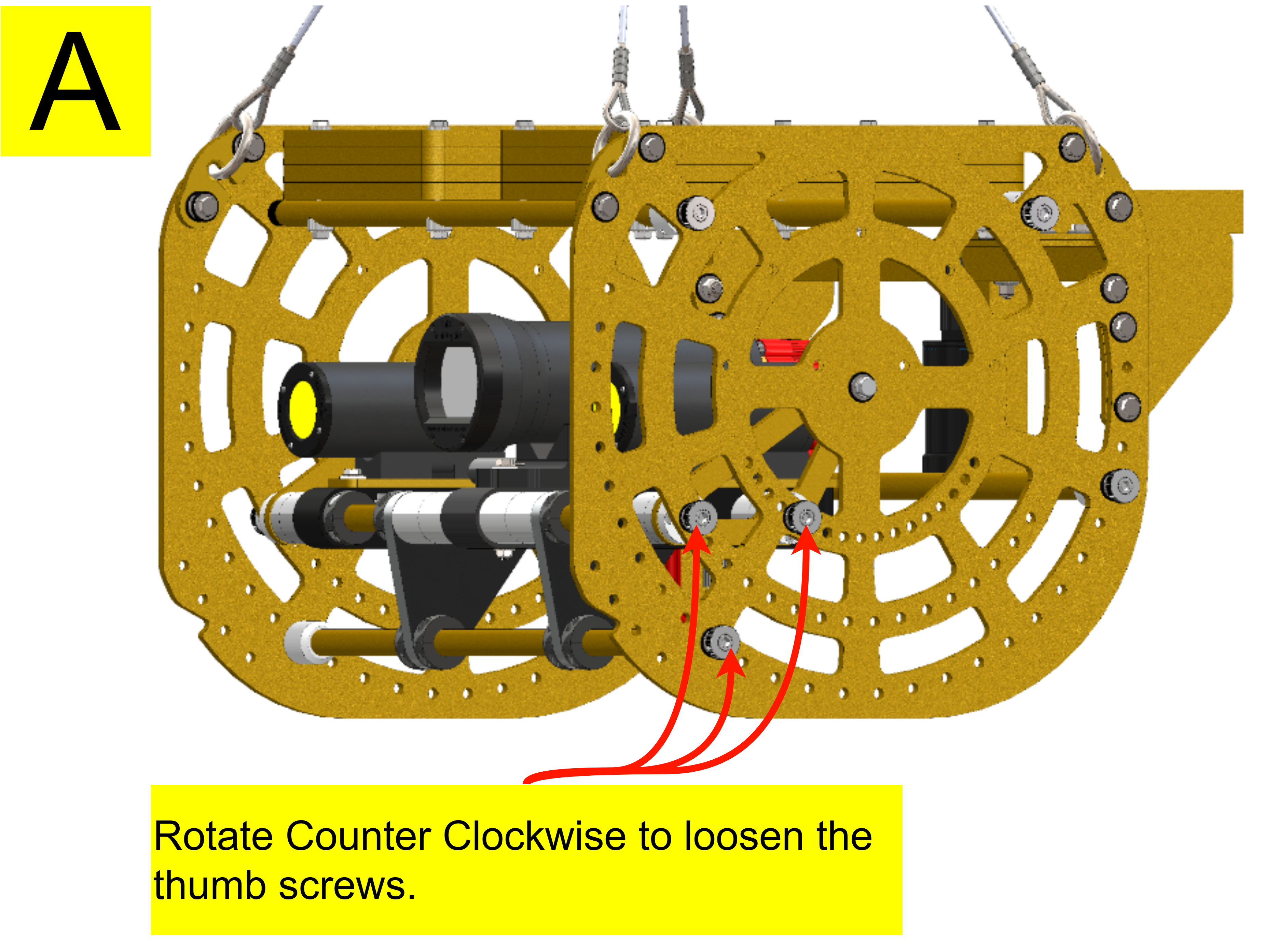
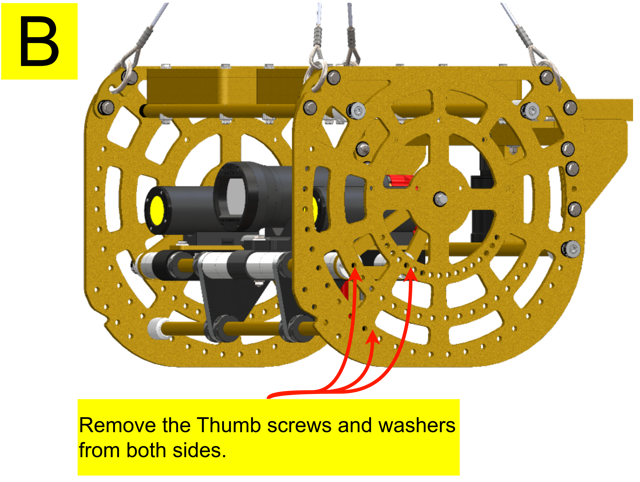
Loosen and remove the pivot panel screws highlighted with RED Arrows in Image A. Remove the steel and plastic washers under each screw head so that it resembles Image B. Repeat this process for the opposite side of the drop frame.
|
|
|
|
|
|
2
|
|
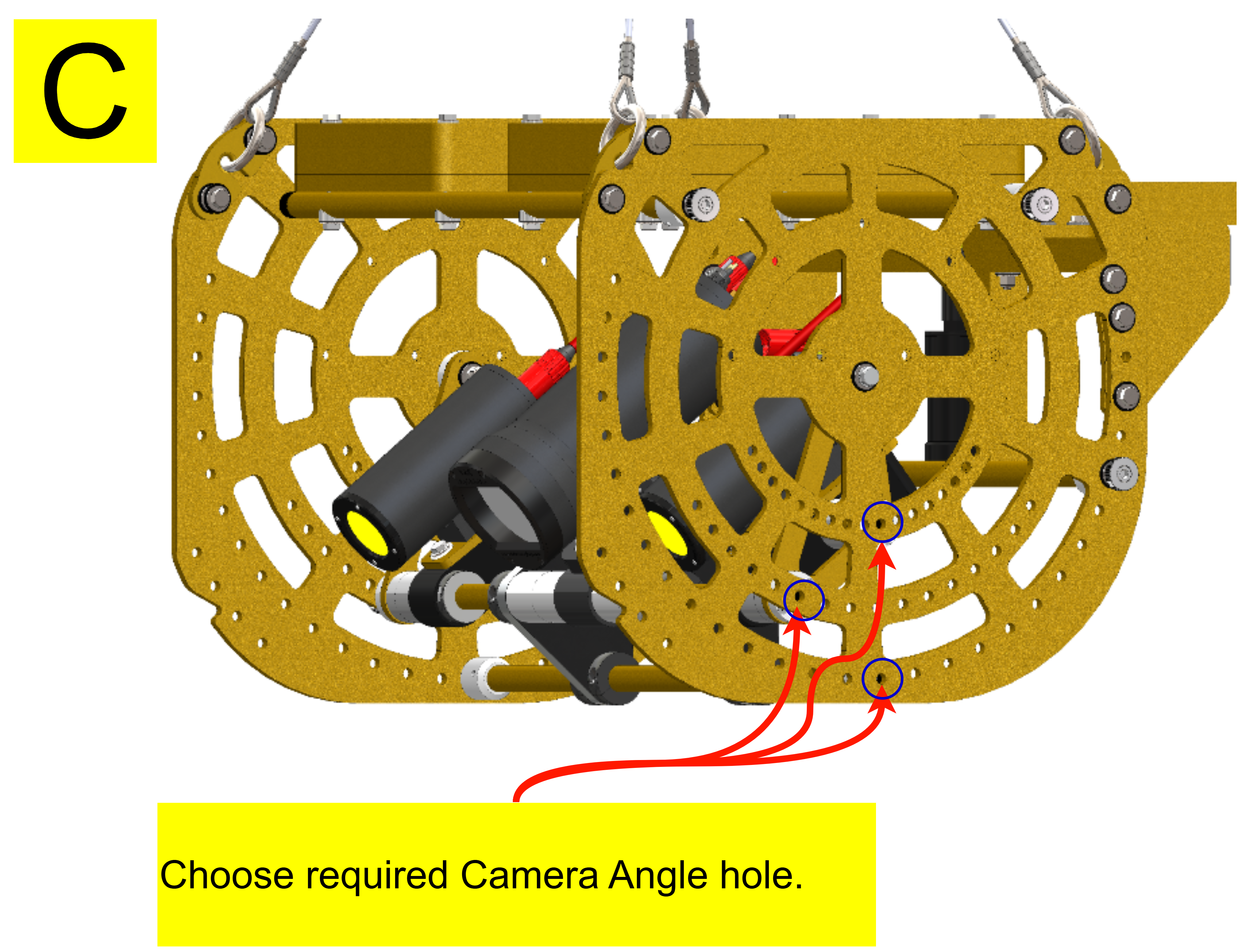
Moving the assembly is a two-person task. With one person on each end of the drop system, carefully rotate the camera/LED assembly as shown in Image C to the new desired position.
|
|
|
|
|
3
|
|
The spacers on the ends of the spars will be loose during this step; hold them in position while moving the assembly. If a spacer is dropped, simply slide it back between the spar end and the support panel. Some force may be required to make the spacer fit. This is shown more clearly on the DCS Camera/LED Pivoting 2 page.
|
|
|
4
|
|
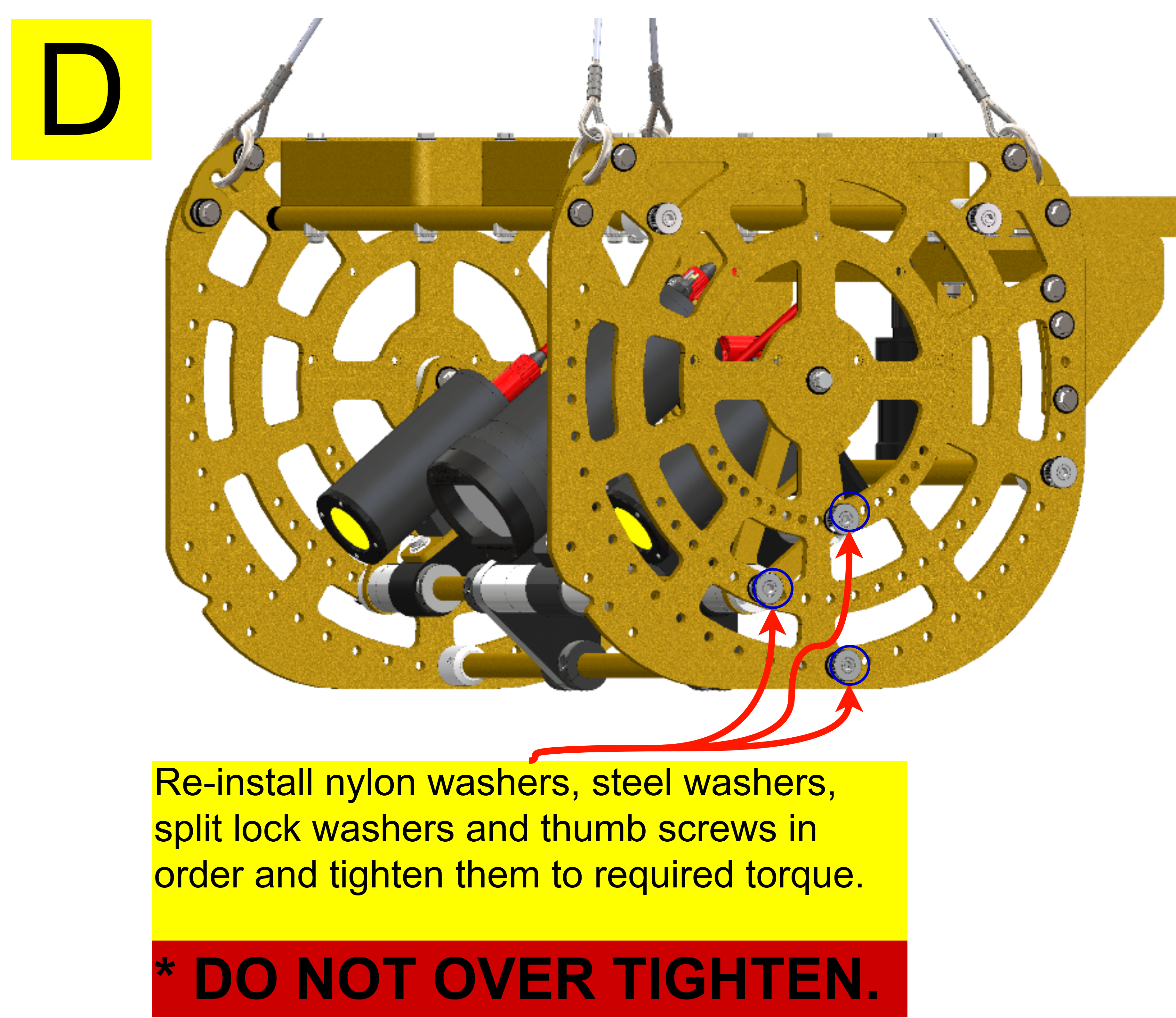
Once the assembly is aligned with the holes in the new position, reinstall the screws removed in STEP 1 on both sides of the drop system. Ensure that the washers are replaced under the screw head. The nylon washer should contact the support panel with the steel washer directly under the screw head.
|
|
|
|
|
Warning:
|
DO NOT OVER-TIGHTEN THE THUMB SCREWS TO AVOID DAMAGING THE THREADS ON SPARS.
|
|