
|
|
|---|---|
|
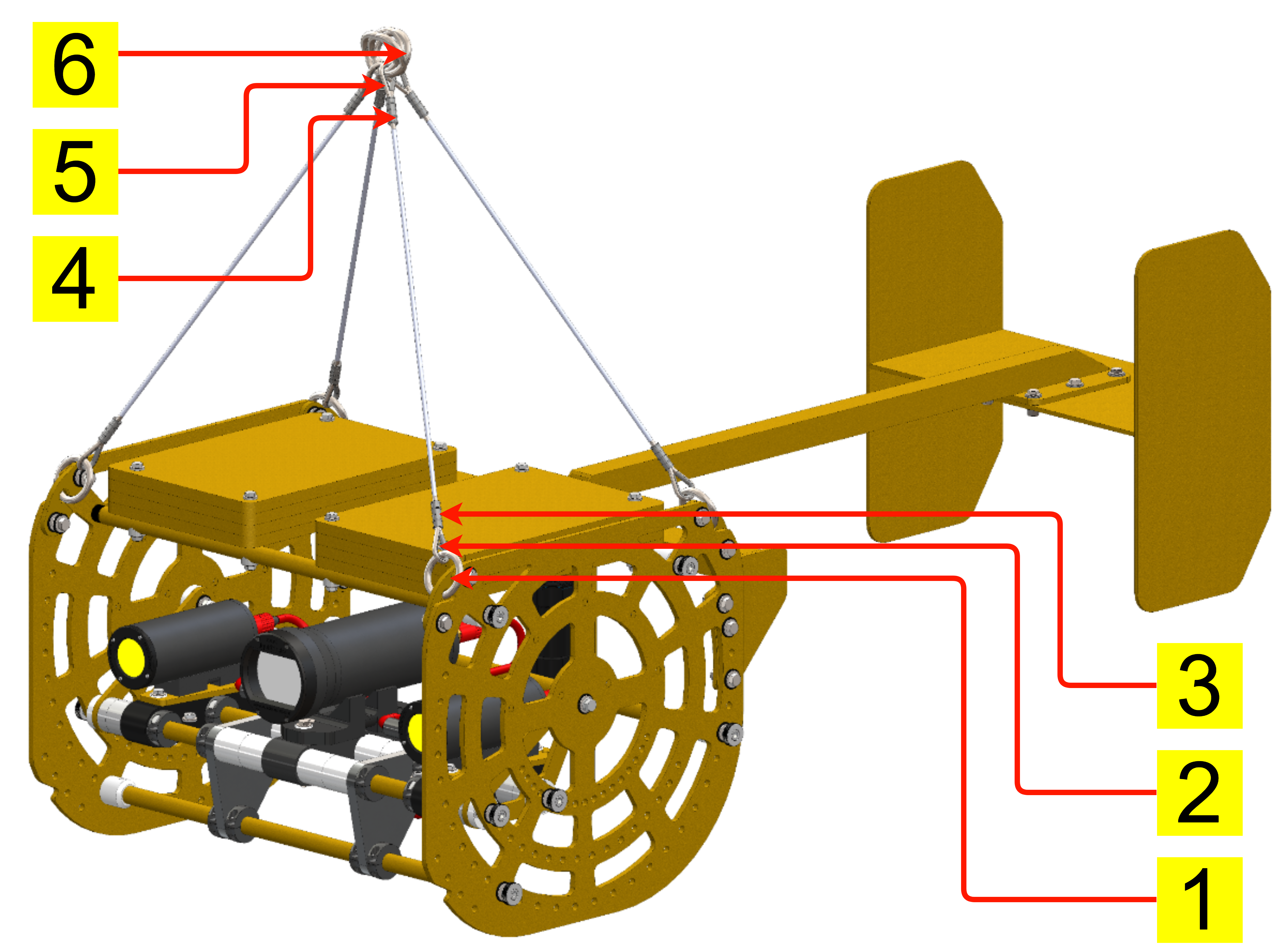
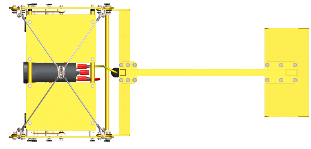
The DCS main suspension bridle is attached to the system at four top mounting points using stainless steel tabs. The bridle consists of wire rope legs that terminate at a central steel ring (1.5” ID) on the upper end. |
|
|
The bridle legs must be securely attached to the four top mounting tabs. This ensures that the DCS maintains a stable, level profile during vertical deployment and prevents the system from twisting in the water column. |
|
|
The components for installing the main bridle are shown in the figures to the right: |
|
||||
|---|---|---|---|---|
|
1 |
Small stainless steel ring (1.5” ID) |
5 |
Bottom Bridle tab |
|
|
2 |
Top Bridle tab |
6 |
Bottom Bridle tab fasteners ((2) sets, 4 per side) |
|
|
3 |
Top Bridle tab fasteners ((2) sets, 2 per side) |
7 |
Main tow bridle junction point (quick link that connects the stainless steel rings) |
|
|
4 |
Large stainless steel ring (2” ID) |
8 |
Main tow line (tied to the junction point quick link) |
|
|
|
|||
|
||
|---|---|---|
|
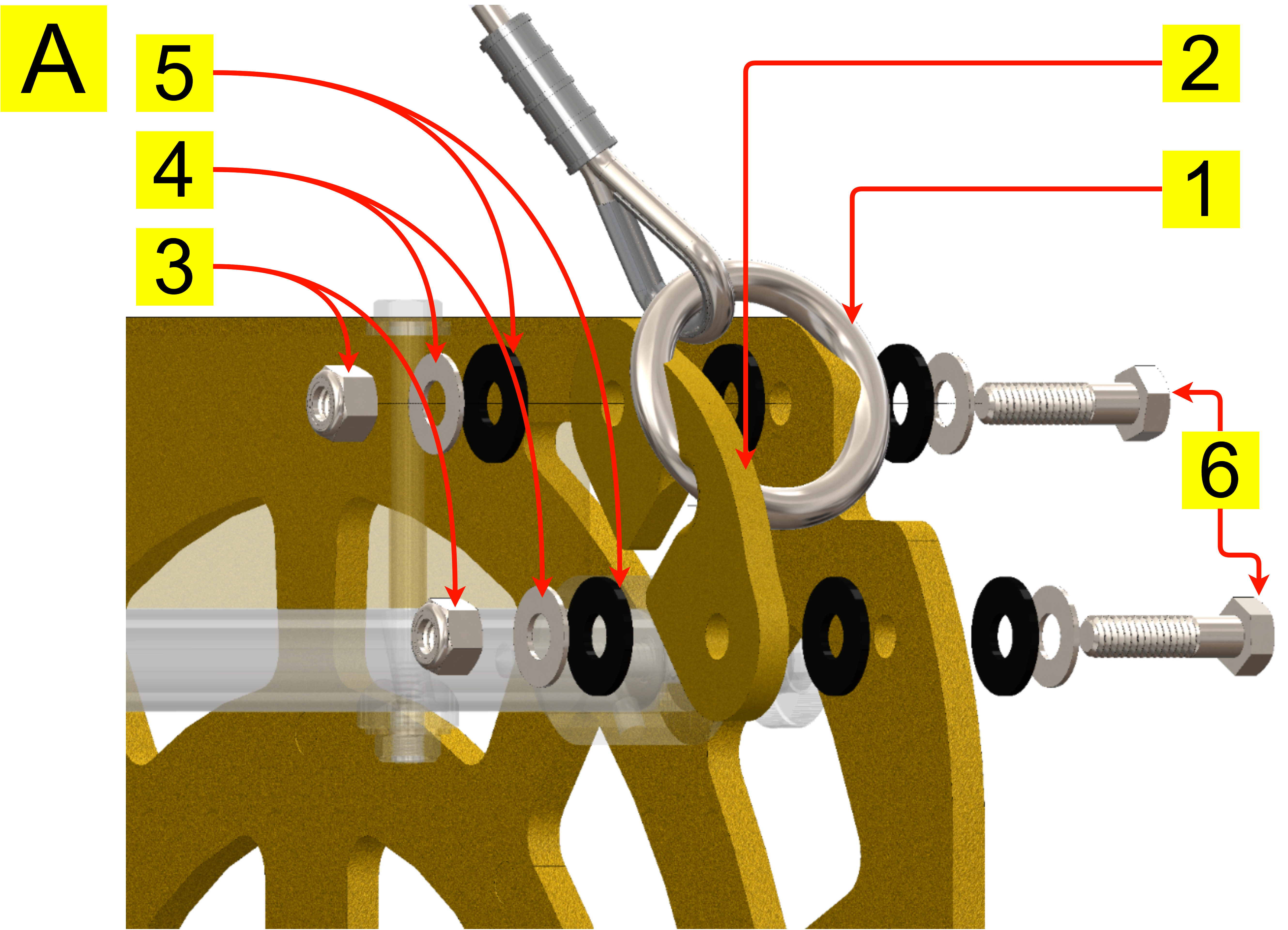
Fasten the bridle tabs together using the same fastener stack combination for each mounting hole. The figures on the right show the fastener order. |
||
|
||
|
1 |
The image to the right shows the bridle tab assembly. Begin by passing the small metal ring ① attached to the longer leg of the bridle pair over one end of the top bridle tab ② until it sits inside the center slotted cutout. |
|
|
2 |
Install the bridle tab fasteners as shown in Image A. The bridle tab screw ⑥ should have a stainless steel washer ④ directly underneath its head, followed by a plastic washer ⑤. Pass the screw through one of the bridle tabs’ holes from the outside face of the support panel. Repeat for the second hole in the bridle tab. |
|
|
3 |
Another plastic washer ⑤ is placed over the screws on the other side of the main support panel. |
|
|
4 |
The metal ring ① and the bridle tab. ② The assemblies are slid over the protruding screws such that they pass through the mounting holes in the tab. |
|
|
5 |
A plastic washer ⑤ followed by a stainless steel washer ④ is placed on the ends of the screws. As a general rule, the bridle tab faces and main support panel surfaces should be isolated from the steel fastener components by the plastic washers. |
|
|
6 |
A locking nut ③ is fastened to the ends of the screws and must be tightened securely. |
|