Deck and Cabin Wiring Diagram
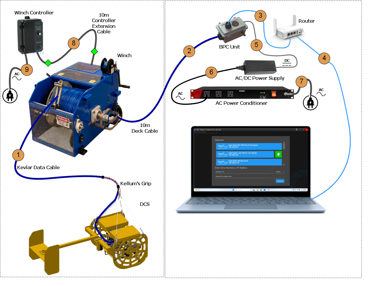
This diagram serves to guide the client/user in properly setting up and testing the product before it is used in live situations. It also helps verify that all necessary equipment is included.
Warning: When testing in Air, do not allow the system to run continuously for more than 5 minutes due to overheating.
System Wiring:
See “Drop Camera System Auxiliary Configurations” for camera/frame wiring
-
Connect the Kevlar Data Cable from the Winch to the Rayfin Coastal Camera
-
Connect the 10m Deck Cable from the Winch to the BPC Unit. It has a 2-pin connector on each end
-
Connect the BPC Unit to the LAN port on the Ethernet Device (router or switch) using a supplied Ethernet cable
-
Connect the Windows 10 or 11 PC to the second LAN port of the Ethernet Device.
-
Connect the AC-DC Power Supply to the BPC Unit
-
Connect the AC/DC Power Supply to the AC Power Conditioner
-
Connect the AC Power Conditioner to an AC Outlet, then turn the switch on both the AC Power Conditioner and the BPC Unit to power up the DCS. Depending on the network setup, it can take up to 60 seconds to detect the Rayfin camera.
-
There is an optional 10m Winch Controller Extension Cable, which can be connected between the Winch Controller and the Winch, or omitted with the Winch Controller remaining attached to the Winch and directly connected to the Winch
-
***SAFTEY***ENSURE THE WINCH CONTROLS ARE IN THE OFF POSITION. Connect the Winch Controller AC Power Cable to AC Power. DO NOT USE THE AC POWER CONDITIONER for the Winch
|
Cable Color Code |
|
|
Blue |
Camera Data / Power |
|
Yellow |
Altimeter Data / Power |
|
Green |
Laser (MantaRay or Skate) |
|
Red |
Aquorea LEDs |
Rayfin Coastal/Kevlar Data Cable
-
The Kevlar Data Cable ① runs through a Woven Kellums Grip to protect its integrity and provide strength.
-
The Loop of the Kellums grip then attaches to the Bridles Drop Point.
-
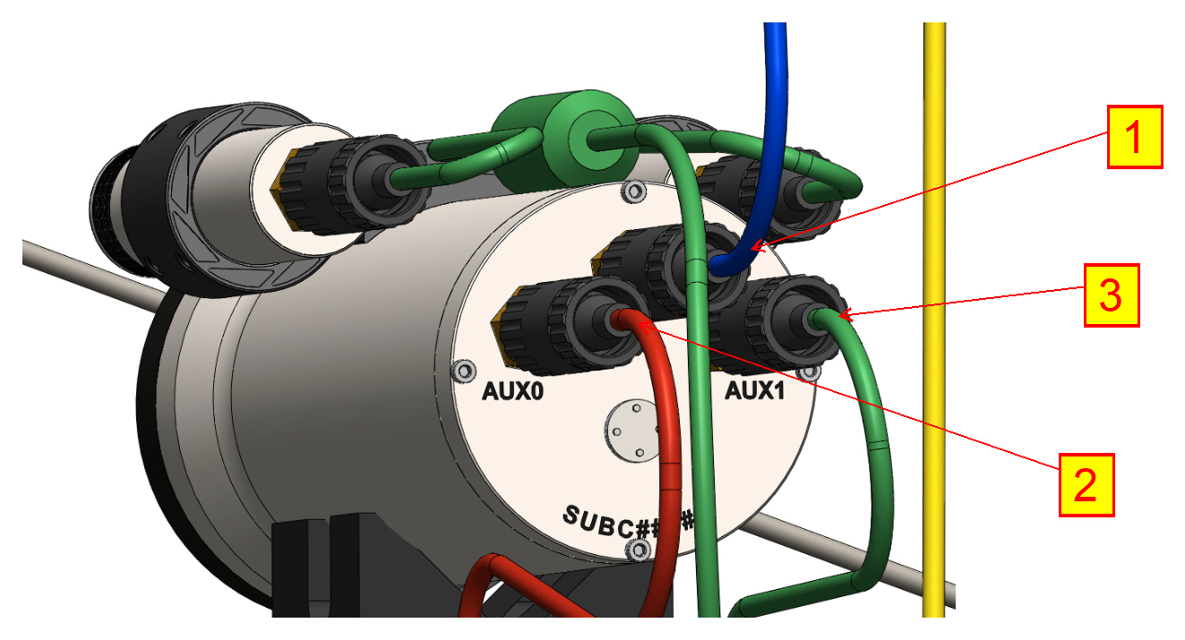
The Cable connects to the central 2-pin bulkhead on the Rayfin endcap.
-
Route the camera cable from the back of the camera along the back-left or back-right bridle. Secure it in place with low-profile cable ties.
-
The remaining portion of the cable is routed upward in the figure; there needs to be enough slack allotted here for cable grip installation so that no matter which way the cable is pulled, the cable grip always takes the force.
Aux Device Cables
-
The cable splice for the LEDs plugs into the AUX0 port ②, and the cable splice for the laser and altimeter plugs into AUX1 ③.
-
Neatly secure the cables in place with low-profile cable ties to the pivot assembly spars/Spacers.
Please note that depicted cable lengths are not dimensionally accurate and are for visual guidance only.