
SubC Drop Camera System is a compact, rapid-deployment solution engineered to deliver high-quality, real-time HD and 4K underwater imagery for marine surveys.
Powered by a single lightweight cable and integrated DVR+ software, this guide provides the essential steps to quickly deploy your system and begin capturing data.
1. What’s in the case!
DCS Case Contents:
|
|
|---|---|
|
1 |
Weight Plates (Optional) |
|
2 |
DCS Main Assembly |
|
3 |
Laptop (Optional) |
|
4 |
Directional Control Tail |
|
5 |
Tail Connecting Spar |
|
6 |
Toolkit / Spare Fasteners |
|
7 |
Aluminum Mounting Base |
|
8 |
3D Printed Positional Holders |
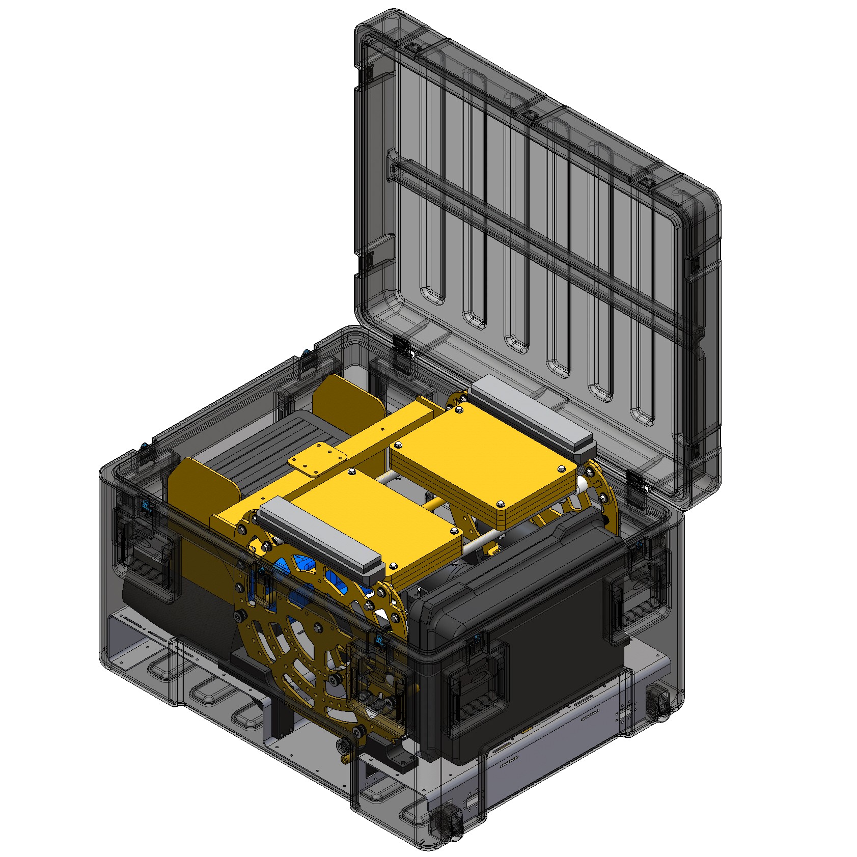
For more details on what is included in the case, please see DCS Unboxing.
Drop Camera System Setup
Once the DCS is completely unboxed, proceed to the following steps before finishing setting up the DCS: |
||
|
|
||
Step
|
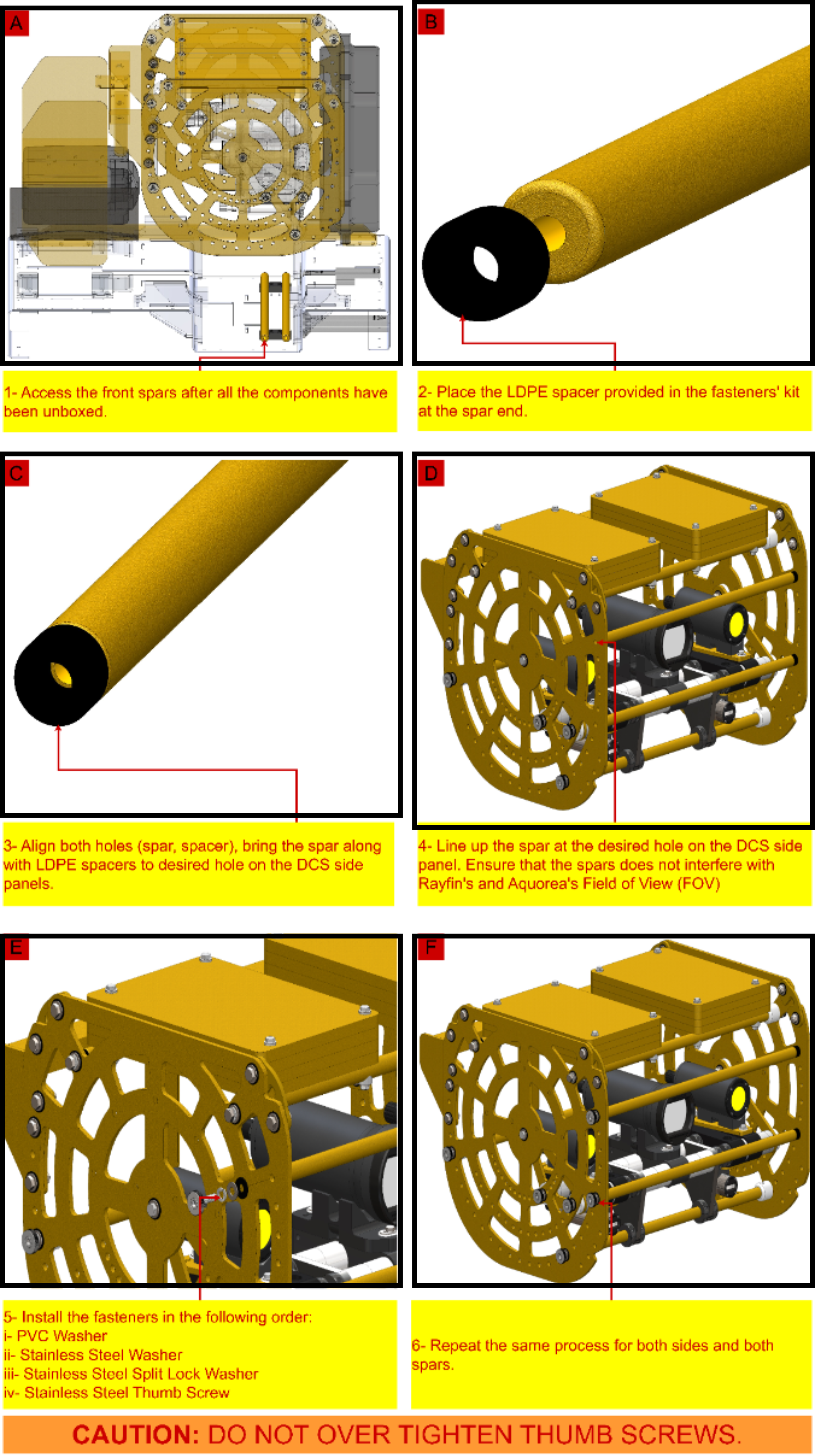
Installing front spars:
|
|
|
A |
After unboxing the components, access the spars secured to the bottom of the mounting base. |
|
|
B |
Align the LDPE spacer provided in the Fastener Kit with the desired installation hole on the DCS Side Panel. Choose a location above and below the camera to protect it and the LED’s from potential impact. |
|
|
C |
Install the hardware provided in the Fastener Kit in the order shown in E in the image. |
|
|
D |
Secure and hand-tighten the Thumb screw on each side for both spars in order. |
|
|
E |
Once the spars are secured, tighten the screws with the provided Hex Key. |
|
Directional Control Tail:
|
||
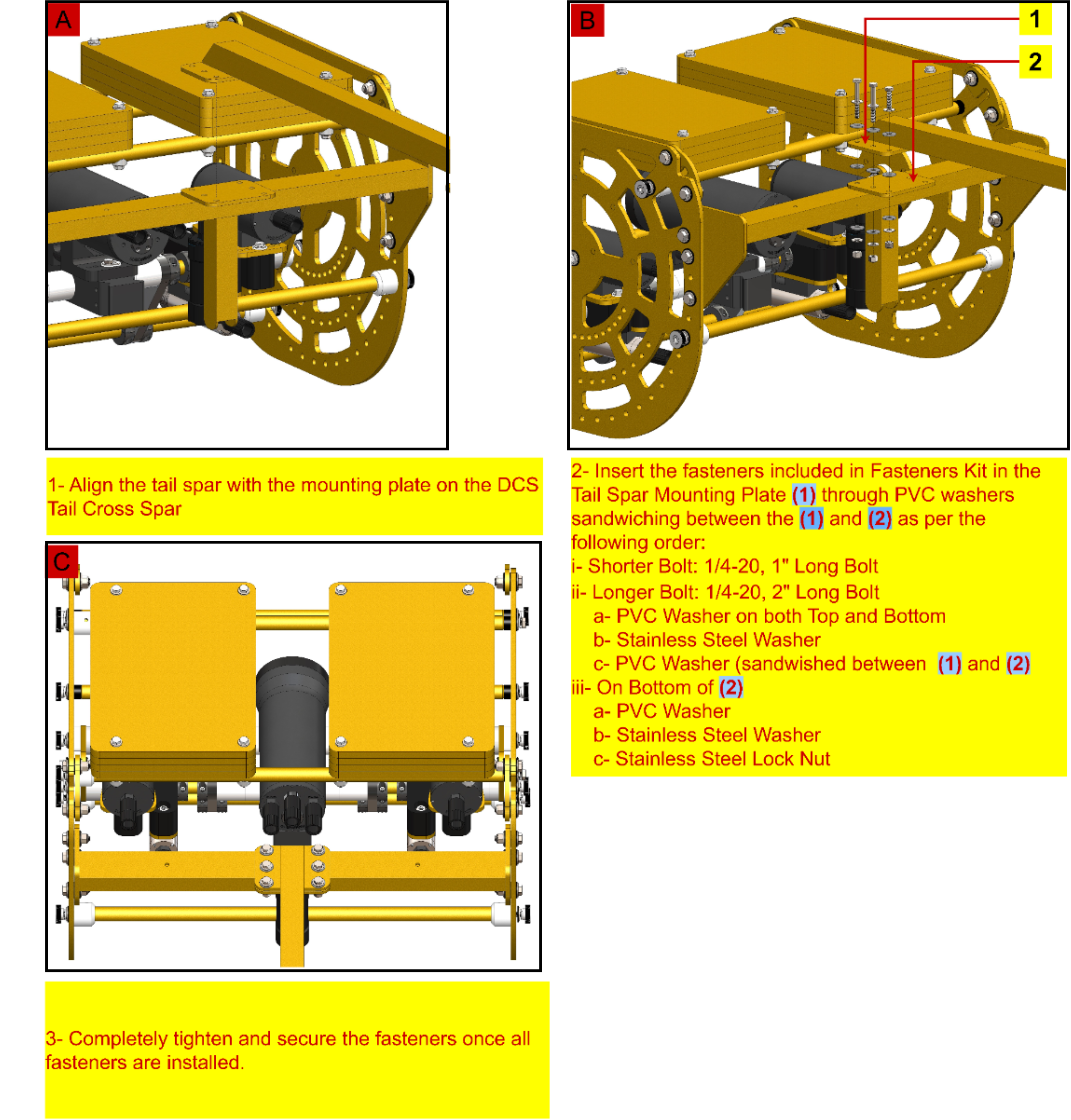
Tail Spar Installation
|
||
|
A |
Align the Tail Spar with the mounting plate on the Tail Cross Spar assembled on the DCS. |
|
|
B |
Insert the fasteners in the Tail Spar as shown in Image B. Ensure you place PVC Washers between Plates 1 and 2.
Once the fasteners have been inserted, hand-tighten the fasteners to secure them. |
|
|
C |
After the fasteners have been secured, tighten the fasteners using the included 7/16” socket. |
|
|
CAUTION: Tail spar uses locknuts. Do not over-tighten locknuts. |
||
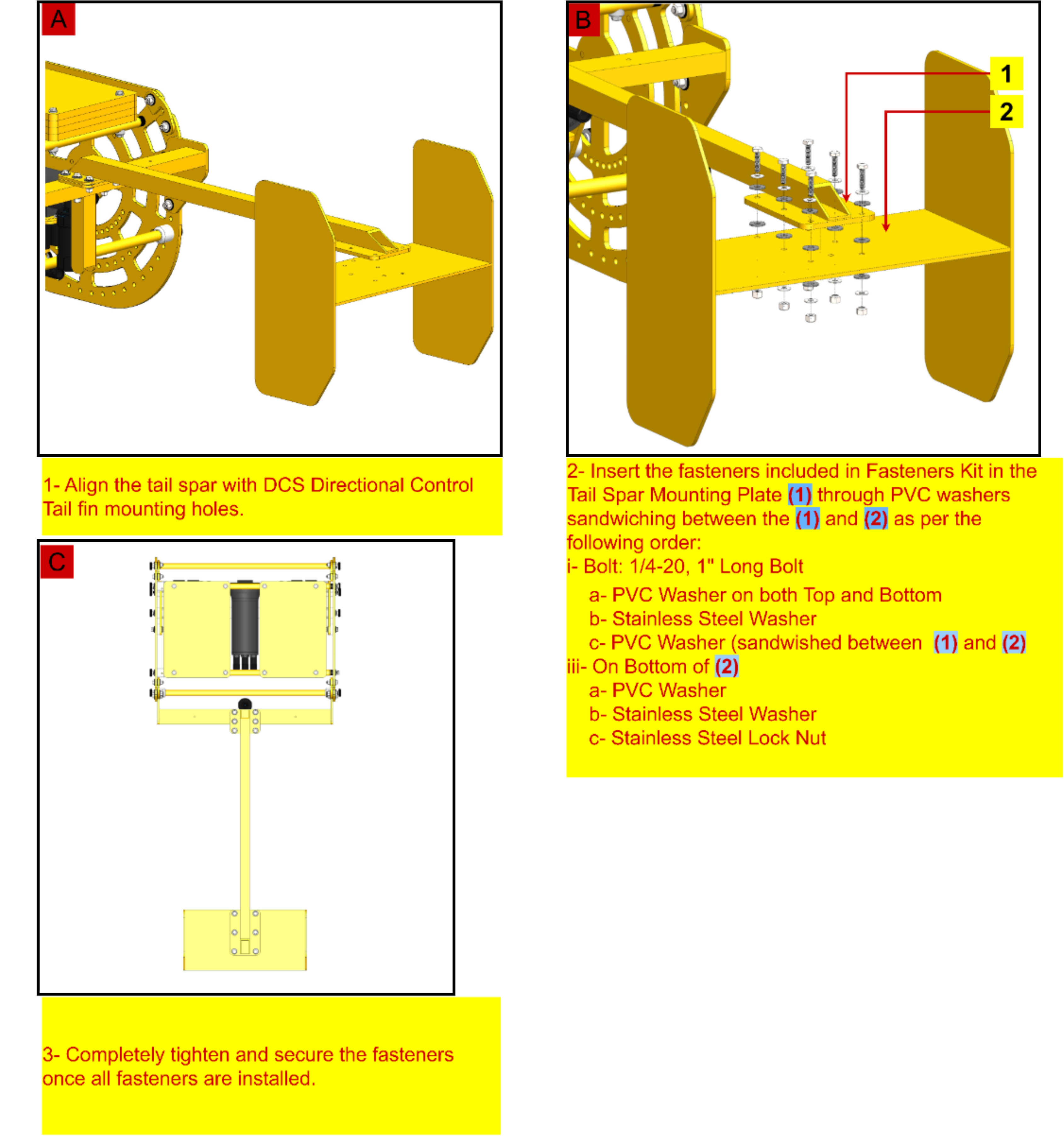
Directional Control Tail Installation
|
||
|
A |
Align the tail spar mounting plate on the DCS Directional Control tail mounting holes. |
|
|
B |
Insert the fasteners in the Tail Spar plate as shown in Image B. Ensure you place PVC Washers between Plates 1 and 2.
Once the fasteners are inserted, hand-tighten them to secure them. |
|
|
C |
After the fasteners have been secured, tighten the fasteners using the included 7/16” socket. |
|
|
CAUTION: Tail spar uses locknuts. Do not over-tighten locknuts. |
||
|
CAUTION: Do not apply excessive pressure on the Directional Control Tail. |
||
Power Cable Routing and Attaching Lifting Points:
|
||
|
A |
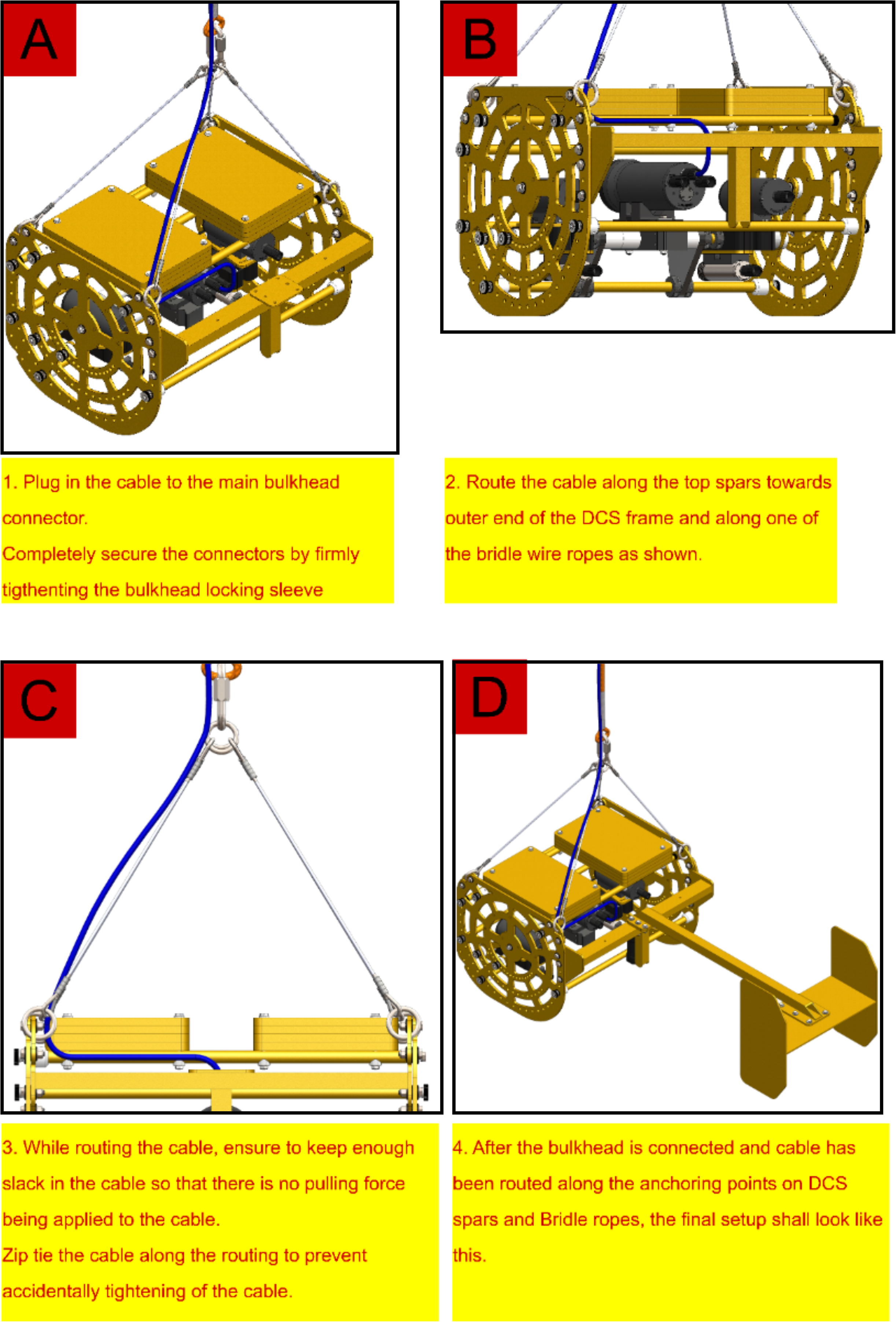
Plug in the Power/Data cable connector to the Rayfin camera bulkhead. If required, grease the connector before plugging in the connector. For more information, please see the section Greasing Connectors. |
|
|
B |
Firmly tighten the locking sleeves. Do not overtighten the locking sleeves to prevent damage to the connectors. |
|
|
C |
Route the cable along the DCS spar towards your desired outer edge as shown in Image B. |
|
|
D |
Route the cable along the Bridle while keeping enough slack to prevent any pulling on the cable. A slack of 2-4 inches over a length of 18-20 inches is recommended.
|
|
|
E |
Continue routing to your desired length along the lifting cable following the slack recommendations given in D. |
|
Kellum Grip installation
|
||
|
A |
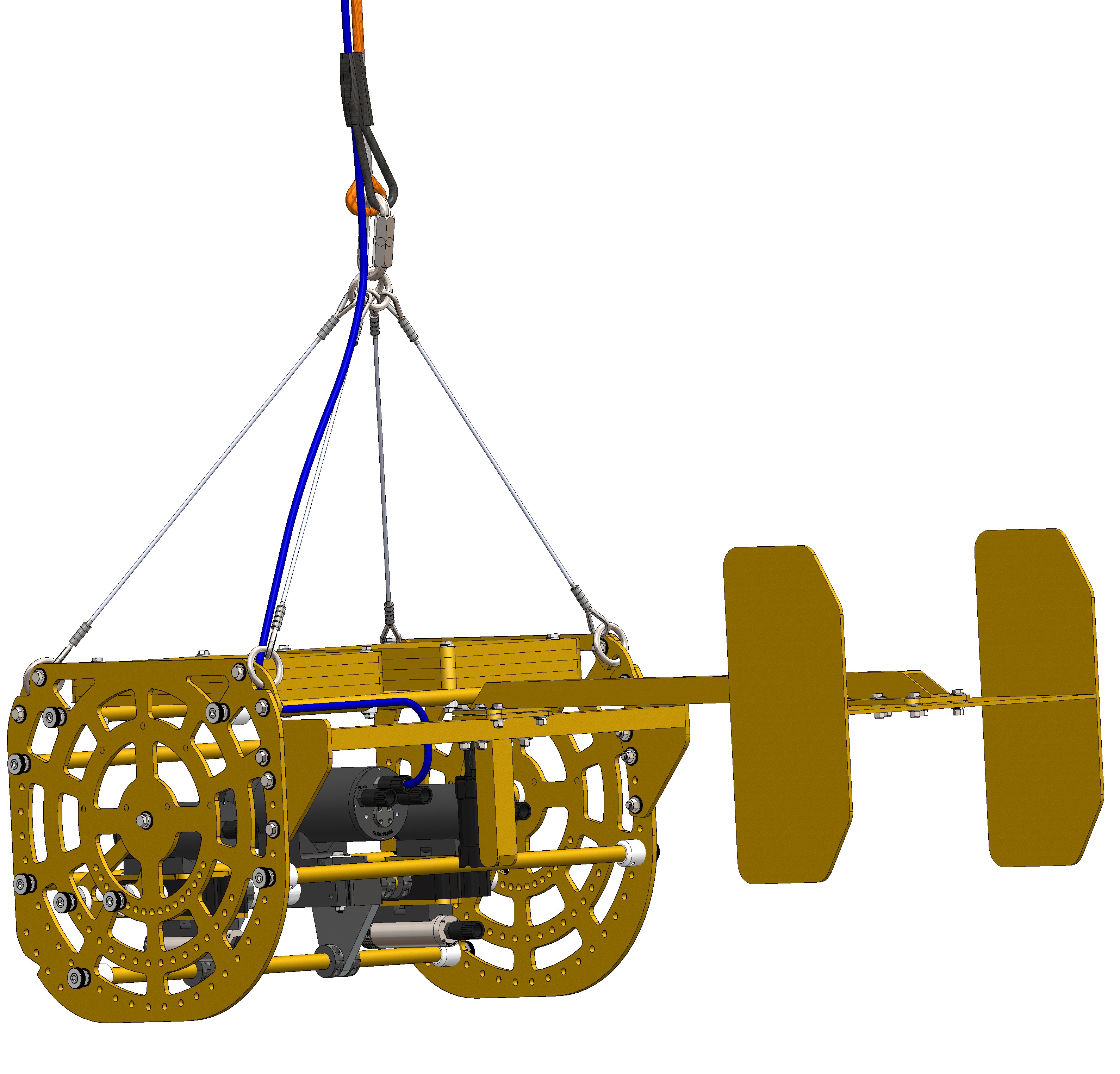
Route the Kellum Grip through the stainless steel quick link. |
|
|
B |
Ensure that there is the minimum recommended slack available in the cable when routing. |
|
|
C |
Image shows the positioning of the Kellum Grip hook and lifting cable hook routed through a stainless steel quick link. |
|
|
For more information, please see Kellum’s Grip section. |
||