SubC Drop Camera System Manual

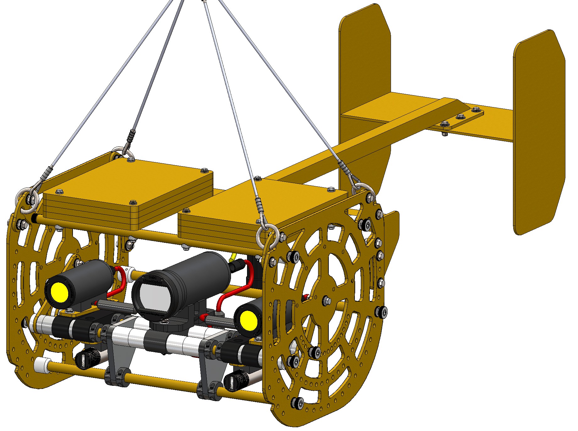
Standard DCS + Optional "Dual" Skate Mk2

DCS w skate.JPG


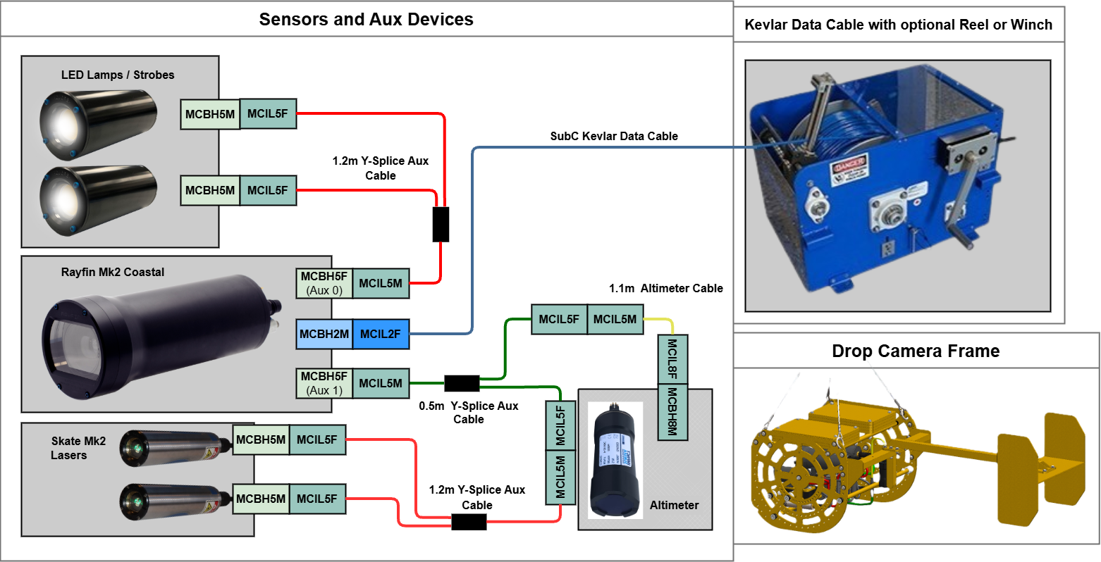
SubC Equipment Connection Diagrams

The purpose of this diagram is to ensure the client/user can properly set up and test before using this product in live situations. It can also be used to verify all pieces of equipment are included.

Sensors & Aux Devices

Cable Routing & Connections

Altimeter

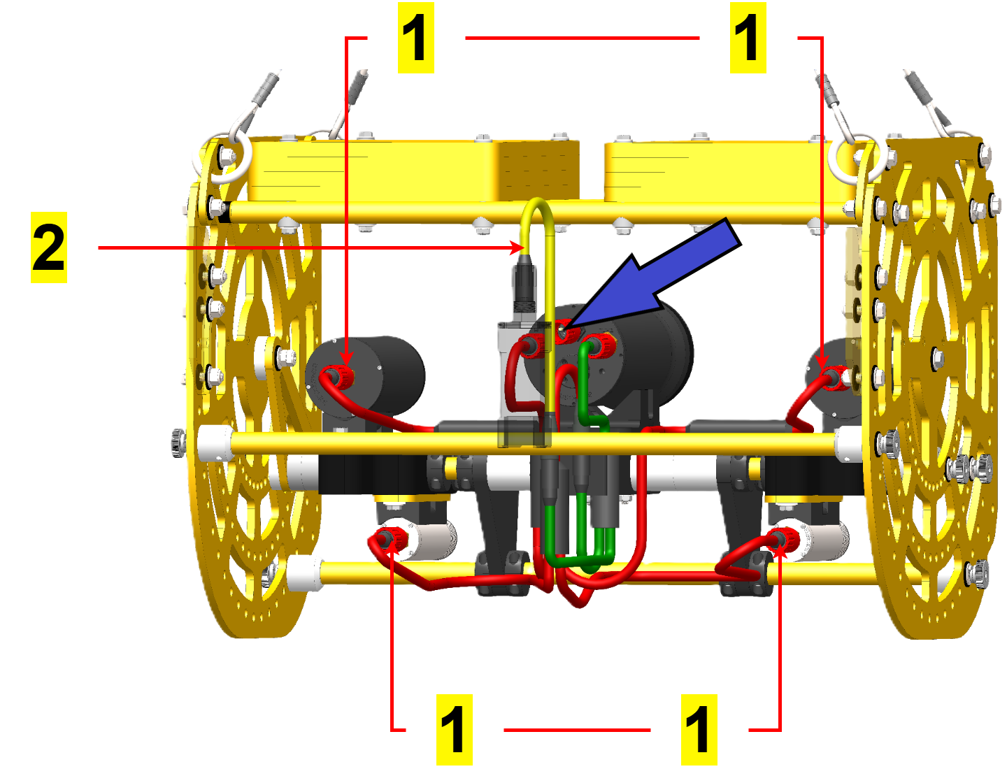
The BLUE cable (shown with a blue arrow in the image below) from the winch connects to the Rayfin camera system in the main bulkhead

    1. The cable passes through a woven fiber Kellums Grip for strength and protection.


93465178-3c22-4166-94e0-76d808c7d240.png


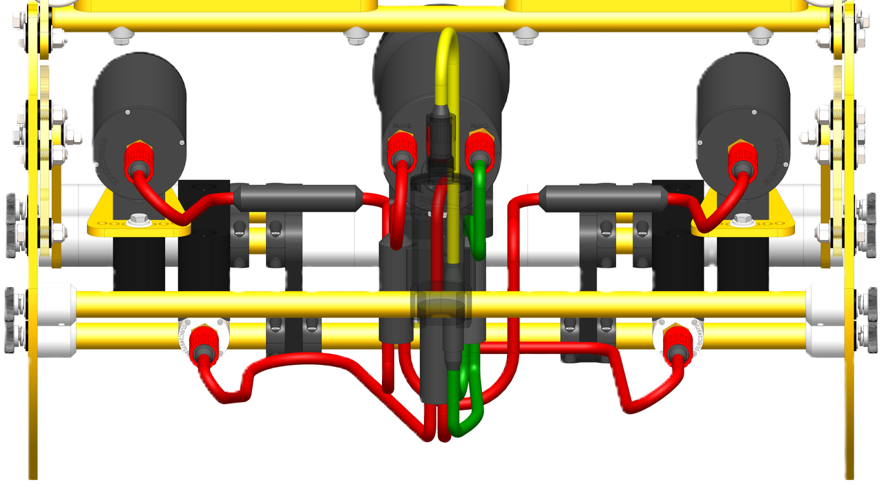
The single end of the RED Long Y-Splice cable connects to AUX 0 of the Rayfin Mk2 Camera. The two connectors at the other end of the cable connect to both Aquorea MK3 LEDs.

The single end of the GREEN Short Y-Splice cable connects to AUX 1 on the Rayfin Mk2 Camera.

    1. One connector of the dual side of the Green Y-splice cable connects to the YELLOW altimeter cable. The MCIL8F side of the Altimeter cable plugs into the bulkhead of the Altimeter.

    2. The other connector of the dual side of the Green Y-splice cable connects to the RED Long Y-Splice cable. The MCIL5F side of the RED Long Y-Splice cable plugs into the bulkheads of the Skate lasers.

Dual Skate Mk2


  1. The 2nd connector of the dual side of the Green Y-splice cable connects to the RED Long Y-Splice cable.

    1. The MCIL5F side of the RED Long Y-Splice cable plugs into the bulkheads of the Skate lasers.


Dual Skate Wiring- Annotated.PNG