SubC Drop Camera System Manual

DCS - Camera and Laser Mount Assembly

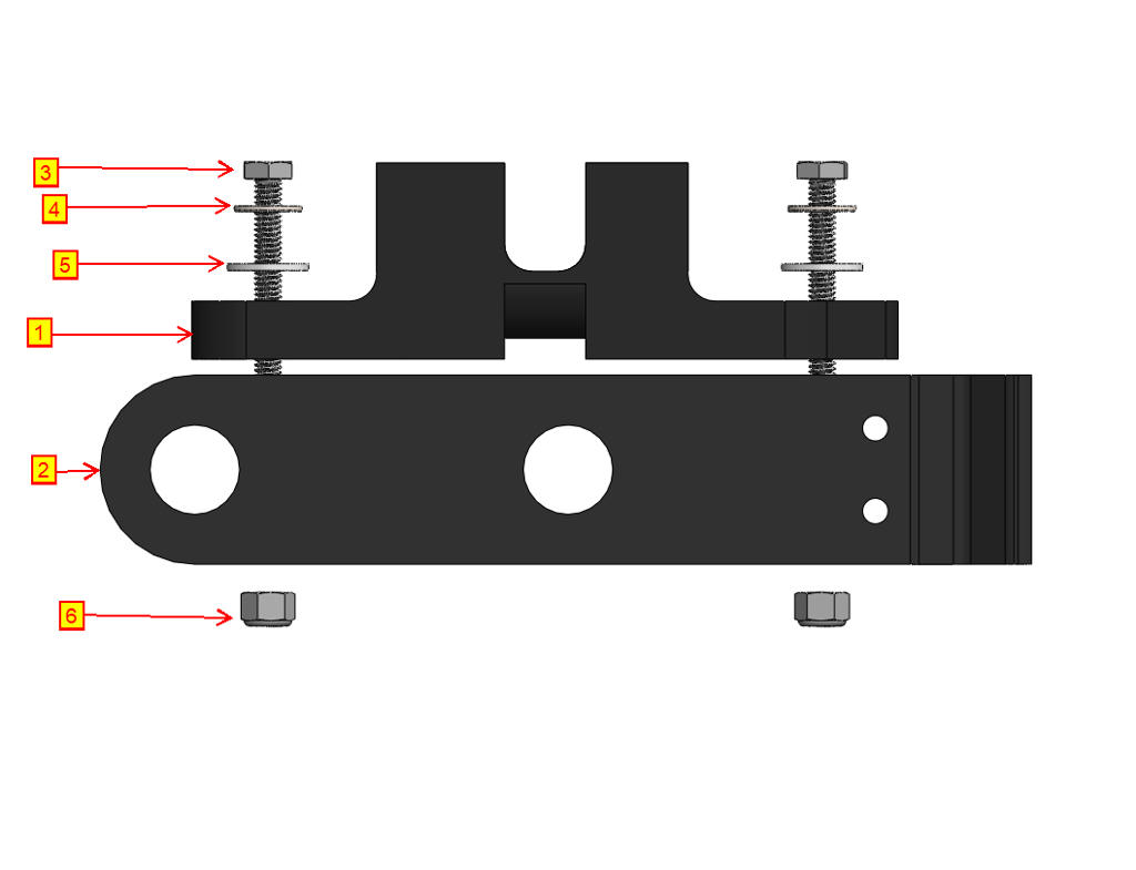
The DCS Rayfin and laser devices are attached to the system using the mount assemblies shown in the images below the instructions.

DCS- Rayfin and Skate Mounting

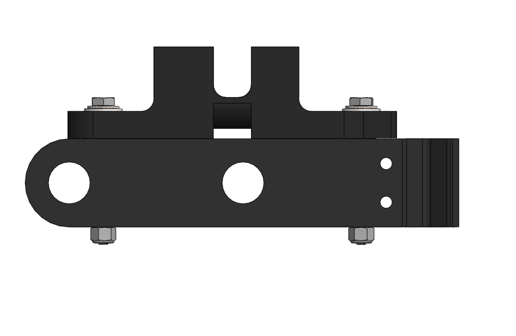
  • Images A and B show an exploded view and an assembled view of the Rayfin/MantaRay mount assembly, respectively. 

A

6f52f63b-5713-4f25-afc9-fedd9f1422db.jpg


B

-camer led 2b.png


  • Place the angled holder top ① onto the angled holder base ②. Center the holes as shown in image B.

  • Pass two (2) stainless steel screws (¼”-20 x 2¾”) ③ through the central mounting holes on the angled holder top ①. Ensure that there is a stainless steel washer ④ followed by a plastic washer ⑤ underneath each screw head.

  • Pass the screws through the mounting holes in the angled holder base ②. On the other end of the screw, place a plastic washer ⑤ followed by a stainless steel washer ④ and a stainless steel locking nut ⑥. Tighten the fasteners so that the assembly resembles image B.


Rayfin and Skate Mount Assembly

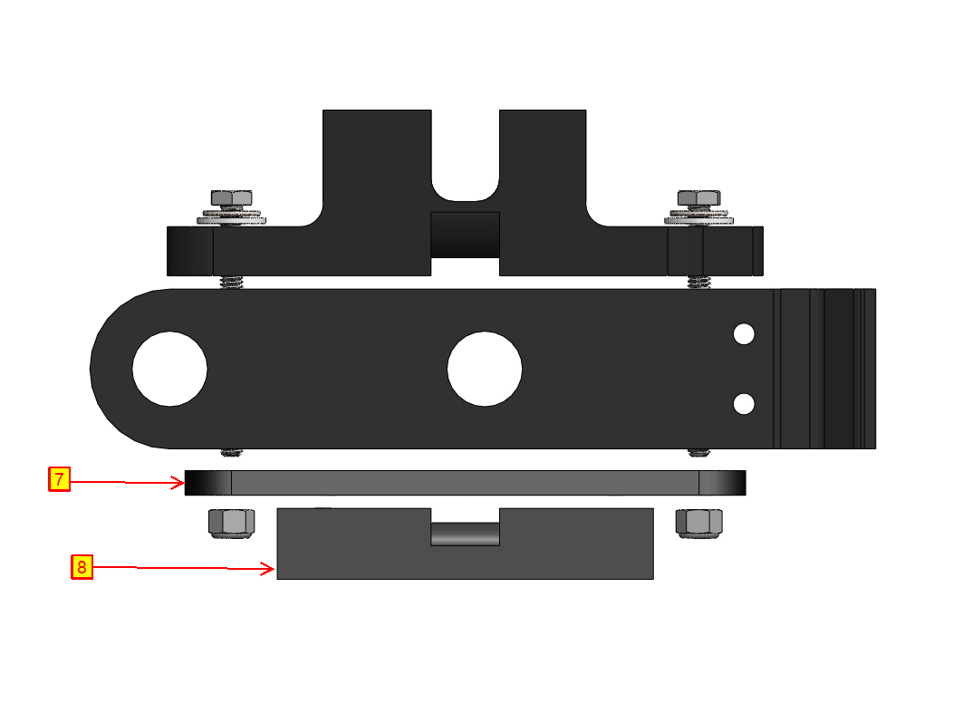
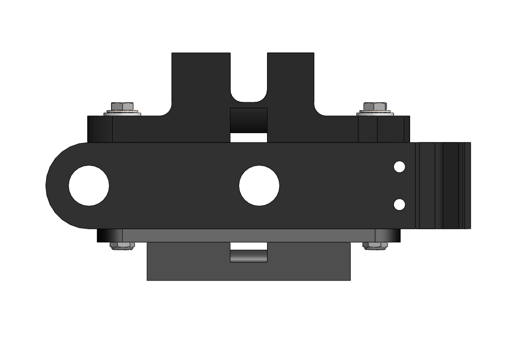
  • The Rayfin/Skate mount assembly follows the same process as described above. The difference is that a newer model of the Skate mount plate and Skate mount base needs to be assembled. Item 7 in Image C is the Skate mount plate that has several holes in specified locations to adjust the laser angles, whereas item 8 is the Skate mount base that joins with item 7, which mounts to item 1.

Tighten the fasteners so that the assembly matches image D.

C

-camera led 2.jpg


D

-camera led 2b.png