SubC Drop Camera System Manual

DCS - Skate Mounting

DCS- Skate Mounting

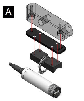
A Skate Mounting.jpg


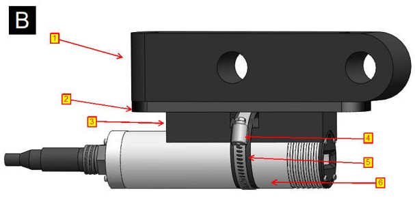
B Skate Mounting.jpg


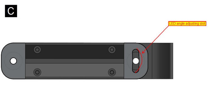
C Skate Mounting.jpg


  • Image A shows the fastening of assembly of Skate mounting components. Item 1 in image B is the common component that mounts the Aquorea LED and Skate lasers. Item 2 as shown in Image B connects to Item 1 and 3 as per the orientation shown in Image A. Note the angle adjustment slot on Item 2 as shown in Image C. The angle of the Skate lasers should be adjusted at the specified slot by losening the fastening nut and adjusting the angle as required.

  • Item 3 shown in Image B is the actual component on which the Skate laser noted as Item 6 on Image B attaches using the provided clamp noted as Item 4. Gap pad noted as Item 5 must be placed between the surface of the Skate laser and mouning clamp to prevent any damage to the surface of the Skate laser and to ensure proper grip.

  • Angle adjustment should be done through Item 2 by losening the fasteners and adjusting the angle.

Note: For any number of Skate lasers installed on the TCS, same instructions must be followed according to the number of Skate lasers installed, e-g for 2 Skate configuration, you will have 2 sub-assemblies of the given components.